In this blog post I will be demonstrating how we can create a TWO NODE failover cluster using Windows Server 2008 Failover cluster capabilities. First part of my blog post will contain information on how we can prepare both nodes before creating a cluster.
First we need to look at basic requirements which need to prepare a Failover Cluster.
- Make storage available to all nodes
- Configure Network adapters on all nodes
- Cluster components to be “Certified for Windows Server 2008”
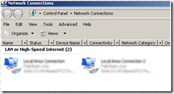
I have configured two networks for Public network and also Private Network.
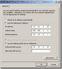
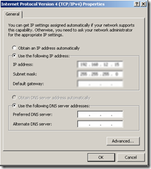
Let’s look at Public and Private network configuration
Public Adapter -> we configure with IP Address, Subnet Mask ,Default Gateway and DNS
Public Adapter -> I will only provide IP Address and Subnet Mask
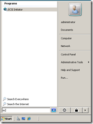
Next let’s proceed and configure Storage Connectivity. I will be connecting to my storage using the build-in iSCSI initiator
After selecting iSCSI Initiator, first it will prompt you to start iSCSI service, which is set to start manually by default on Windows Server 2008 / Windows Server 2008 R2.
After that we need to allow iSCSI to communicate through Windows Firewall. This will be automatically configured for you when you select Yes
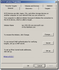
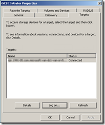
After this step, you will find iSCSI initiator properties.
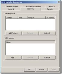
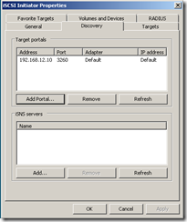
Navigate to discovery tab and select “Add Portal” option for us to connect with our shared storage
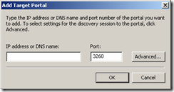
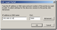
We need to provide with an IP Address or DNS name for iSCSI target
Once we enter required information, we can proceed
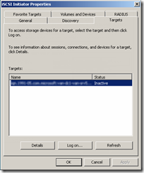
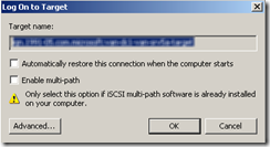
Next we need to navigate to Targets TAB which will allow us to connect with the storage. Select Log on option
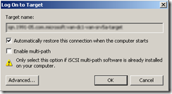
We need to allow following options when connecting with the storage
– Automatically restore this connection the computer starts
After completing this step, we have now successfully configured our storage connectivity.
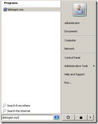
Let’s go ahead and prepare disks using DISK Management utility
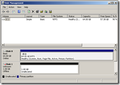
After accessing DISK management console, we can notice that there’s a new DISK added .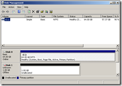
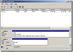
We need to right click on the DISK and bring it ONLINE
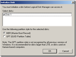
After we bring this DISK online, we can then go ahead and initialize this disk
We need to select which disk, we need to initialize so that it can be access by Logical Disk Manager. We will configure this disk as a MBR style partition disk
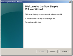
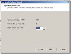
Now that we can access this disk, we will go ahead and create a volume
In this window, we will be specifying the size of the disk
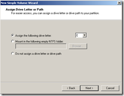
Next we need to select a drive letter
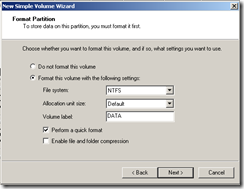
Next, we need to change the volume label, and also select “Perform a quick format” option
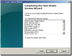
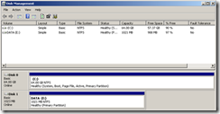
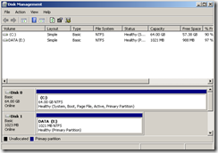
Now that we have already configured, it’s possible for us to view this disk from Disk Management console
Now let’s move to NODE 02, on NODE 02 we need to bring DISK 1 online, which we have already configured on NODE 01
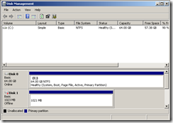
After refreshing disk management console, we can see that it’s no more in unallocated state, so we only need to bring it online now
Since we have completed configuring both disks, Next we will proceed and run validation using Failover Cluster Management console. Before proceeding, we need to go to Server Manager on both servers and install Failover Clustering which is located under features section.
In my next blog post I will publish how we can run Failover Cluster Validation Tool and validate configuration.
